Research: Can AI do Revit? Generative AI to Revit Workflow
Research · Chapter 1 of 7
A dollhouse from one sentence
I asked Gen AI for a dollhouse, and Revit started building it by itself. The hard part came after: it couldn't see what it had built.
Part
I · Typing a house into Revit
Reading
4 min read
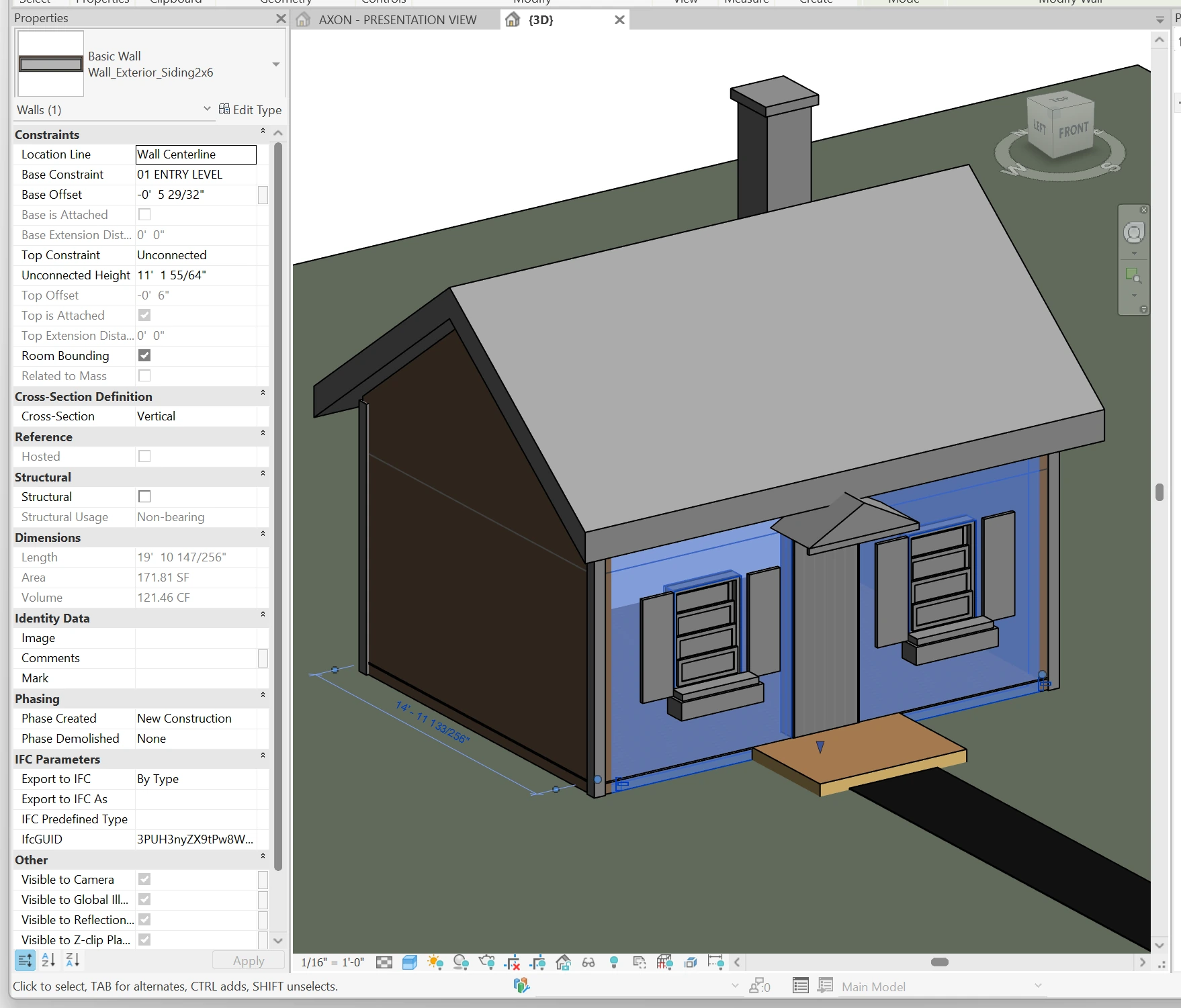
Revit was open on my second screen, and I wasn’t touching it. A wall appeared, then another, then a gable roof, a door with a little pediment, two shuttered windows and a chimney. The mouse never moved… I just sat there and watched.
I had asked Gen AI for a dollhouse with two windows and one door. It built one in Revit, out of real Revit walls.
Figure 1.1. The dollhouse, built from one sentence. The panel on the left is the selected wall’s properties: its type, height and base level. It’s a real wall, and Revit knows it.
I should say where I started. I’m an architect, not a programmer. I’d heard the hype about Gen AI for as long as anyone, mostly from people selling something, and I’d filed it under chatbots that write very confident emails. My big hope was that it might one day rename three hundred views while I refilled my coffee.
A machine designing a building seemed out of the question, because a building is a thousand decisions that have to agree with each other. So I started with a toy.
Figure 1.2. Four chapters from now, the machine would build this whole house in real Revit walls, windows and doors. The elements in blue are selected.
How a sentence reaches Revit
The trick is a plug called MCP. It lets Gen AI use other programs: send them commands and read back the answers. Someone in the Revit community had written one for Revit and given it away. It does what you would do with the mouse, placing walls, loading families, setting parameters, only from text.
For a designer, that’s all there is to it. You describe a thing, and Revit does it. (The wiring is in Part II, for anyone who wants it, and the whole setup is drawn at the end of this chapter.)
A sofa on the lawn
Then I made the mistake every architect makes with a new tool: I wanted it to look good.
A good rendering needs furniture, so the machine went shopping. It installed one rendering program, then another, and uninstalled that one before it made anything. It converted free sofas for a third, and they came in as white boxes. It wrote a little drag-and-drop app for placing furniture, with its own code repository, which I then asked it to delete.
At one point I told it, as plainly as I could, that I wanted something robust, not something fragile. It agreed, and then tried something else fragile. lol
Figure 1.3. It has two windows and one door, as ordered. The sofas are on the lawn, and the white boxes by the door are also sofas, in spirit.
Some 2,450 turns of conversation later, the furniture was solved by one rule: import it one particular way, and only that way. None of it had anything to do with design. I was hooked anyway, because it had built a house I never touched.
“Your screen seems to be locked”
Behind the furniture there was a real problem. The plug could build, but everything it sent back was a list of element numbers, parameter values and the name of the open view, and never a picture. Whether a wall met the roof, the machine could only guess from numbers.
So it asked to see my screen, and I said yes. It took a screenshot of Revit and reported, very politely, that my screen seemed to be locked, so it couldn’t click.
I was sitting right in front of it… The screen was on, unlocked, showing Revit.
What reached the machine was a black rectangle, and it drew the only sensible conclusion from a black rectangle. Then, trying to bring Revit to the front, it started a second copy of Revit, and it did that more than once.
It was funny the first time. By the fifth black frame it wasn’t funny anymore, because a machine that can’t see Revit can’t check what it builds in Revit.
A second pair of eyes
The fix came from Autodesk, which had begun to preview its own plug for Revit. That one can’t build a single wall. What it can do is export: give it some views and a folder, and it writes the pictures.
So now there are two plugs. One builds, the other takes the photograph, and the machine opens the photograph and looks. The first test made a neat little demonstration: it built a test box beside the dollhouse, exported a view, saw the box standing there, and deleted it again.
Every Revit job since runs that same loop: build, photograph, look, fix. And the first rule the machine reads about its own work is the obvious one: look at every picture before saying it’s done.
Figure 1.4. The whole setup, as it ended up: one plug to build, one to take the picture, and a look before anything counts as done.
So, can it design?
It could build a wall, and it could look at the wall. What it couldn’t do was tell a good wall from a bad one. That’s what architects spend years learning, and I wondered if the machine could learn it faster.
A sensible architect would have closed the laptop here. I didn’t, obviously.
Research · Chapter 2 of 7
Architecture school in a text file
I tried to teach it taste: 308 rules, pretty pictures, a final exam. The scores never closed the gap, and nobody had looked at the outside of a house.
Part
I · Typing a house into Revit
Reading
4 min read
So I asked for a real house. It came back fast and thorough: about thirty sheets of construction drawings, wall assemblies and junction details included. It was also headed the wrong way the whole time.
Both beds floated in the middle of their rooms. One bedroom had no closet. The lobby was 397 square feet, in a house!
None of these are hard problems. Anyone a few years out of school catches them on the first pass. The machine could build, and now it could see, but it couldn’t judge.
I couldn’t send it to architecture school for five years. So I wrote it the textbook instead… how hard could that be?
308 rules
We measured 74 built homes whose plans I admire: hall widths, door positions, the space beside a bed. The machine turned the measurements into rules, each with its evidence. Put the hinge 3 to 17 inches from the corner. Head the bed on a blank wall, windows to the side. It read like the margins of a very particular office standard, and it grew to eighteen books and 308 rules.
Then we graded it. A designer agent drew a plan for a real lot it had never seen, and a critic agent scored the plan blind, on twelve criteria. The critic also scored the house that had actually been built on that lot. If the rules worked, our plans would close in on the real ones.
They never did, even as the rulebook grew from 237 rules to 308. The scores rose on one lot and fell on another.
Figure 2.1. More rules brought our plans no closer. On every lot, the house someone actually built beat our best plan by about four-tenths of a point.
When we counted which rules the designers had actually cited, nearly half had never been cited once. The rule broken most often was the one about the hinge. Of course it was.
The rulebook knew how wide a hall should be. It knew nothing about why you’d want to walk down it.
Pretty pictures
If rules couldn’t teach taste, maybe pictures could. That’s how architects absorb a style: by looking at a lot of good houses. And image generators make pictures instantly. So we built a test lot in Revit, with the neighbors, the fence and a big oak in the middle, and asked the generators for concept sketches.
On the site model, the oak was the stand-in every architect draws: a glass drum for the canopy on a thin post for the trunk. The two most expensive generators obeyed the prompt exactly. They kept the glass drum, and wrapped the house around it.
Figure 2.2. The courtyard wraps the drum as if the drum were the point of the whole design.
The cheaper ones grew the drum into a tree and cut a perfect oval in the roof for it. Then they added a mountain range, for mood lol. Under the oval, the sunlight falls on the paving as a rectangle.
Figure 2.3. It’s lovely, and not one line of it could be measured.
Image generators kept one job in my process, and it’s at the very end: rendering a house once its drawings exist, and never before.
The final exam
I wanted a straight answer, so we set an exam: one lot, one brief, four designers with different instructions.
Purpose got a short statement of what a good house is for, and a few example houses.
Rulebook got all 308 rules.
Small Rulebook got the same rules on a smaller, cheaper machine.
Checker designed from the purpose, then corrected its draft against every rule.
I graded the four houses without knowing which was which. Purpose won, and honestly by a lot. Checker came last: it had gone through its design rule by rule and reset the window sills one at a time, and never once looked at a wall as a whole.
Figure 2.4. The more the rules were applied, the more the windows scattered.
The grading taught me more than the grades did. When I looked at the four houses from the street instead of from above, every one showed the street a single small window, and every one used six to eight different sill heights.
The designers had worked from the plan, and none of them had drawn an elevation. Nobody had looked at the outside of the house. No rule could catch that, because the rulebook was about rooms, and a facade isn’t a room.
The wrong question
I tried a few more things. The machine read eleven books and papers on how designers think, and wrote what it called a canon, comparing it, in its own notes, to a religious commentary (yes, really). The house it designed after reading the canon came out seven square feet different from the one it designed before.
Then I noticed what all these attempts had in common. Every one was about what the machine knew, and none changed how it worked. It worked in Revit, where every look at the house cost a tool, a parameter and a dialog box.
What it needed was a cheaper pencil.
Research · Chapter 3 of 7
A cheaper pencil
In Revit, every look at a house is expensive. So the machine writes its drawings as text, a program draws them, and Revit comes last.
Part
I · Typing a house into Revit
Reading
3 min read
Until then, every house the machine designed ended up in Revit as a white model: plain boxes with rectangles cut into them, a flat plate for each roof, and a tall glass cylinder around the oak. We called it tofu, and it was about as exciting as it sounds.
Figure 3.1. This is tofu. It says where the masses go, and nothing about how a wall meets a roof.
Tofu was quick to make, and it told me almost nothing. Once the machine framed three different houses, and from the street all three read the same: a garage door, an entry door, a flat white wall. The boxes flattened the design to what boxes can say.
Where the energy went
Watching the machine work in Revit, I could see where its effort went: which family, which parameter, which view, which dialog box was blocking everything. All its energy went into operating Revit, and none was left for the space.
That isn’t how architects design. We don’t start in 3D. We draw a plan, cut a section, find out what the plan hid, and go back to the plan, a few dozen times, and then we draw the elevations. The 3D comes last, mostly as a check.
Design is a loop of looks, and a loop is only as good as the price of one look.
Figure 3.2. The same effort buys three looks and a guess with one pencil, and a hundred looks with the other.
Drawings, dictated
The machine can’t hold a pencil, so it dictates. Each drawing is a short text file that reads like a drawing described over the phone: a wall from here to here, six inches thick; a window in it, sill at three-foot-seven-and-a-half. A program draws exactly what it hears, at scale, as a real CAD drawing that links into Revit.
Figure 3.3. Four lines of text, and the drawing they become. The third wall was written five inches short, so it’s drawn five inches short.
It draws nothing more than that. If a wall stops five inches short of another, the drawing shows the gap. A program that tidied things up on its own would hide the machine’s mistakes from the machine, and from me.
The machine wrote that program too, round by round, and each round started with something I’d said about a drawing. It grew to almost six thousand lines. I have never read one of them… and honestly, I don’t plan to. I judge the drawings, and the drawings tell us both whether the code works.
Figure 3.4. Nobody modeled this. The text behind this view is 265 characters: where to stand, which three plans to build it from, and a title.
Each time it draws, the program builds the whole house in 3D from the plans, uses it to draw what you would see, and throws it away. So the plans are the only source of truth. Change a window in plan, and every section, elevation and axon that sees it changes too. On the way, the program lists every place two drawings disagree, to the inch.
Now one look costs a short text file and a moment of drawing. That was huge for me.
Revit comes last
That rewrote the process around four stops: the idea, the massing, the drawings and the model. Between the stops, the machine works. At each stop, I decide.
Figure 3.5. This is the process on one sheet. The massing and the drawings go around as many times as they need, because paper is cheap.
Revit is the fourth stop, and only I can open it. Until I say so, the model waits.
Revit isn’t the villain here. It’s where a building becomes buildable, with layered walls, real families and construction, but it isn’t where a design is found.
The process was ready. It needed a house, and I gave it a ridiculous one.
Research · Chapter 4 of 7
Oak tree, 70 feet in the air
A giant oak on a narrow lot gets four houses, a lot of no, a window system that answers it, and a Revit model with every tree in the sky.
Part
I · Typing a house into Revit
Reading
5 min read
The lot was 60 feet wide and 120 deep, with the street on the short side. In the middle stood a coast live oak with a canopy forty feet across, two-thirds of the lot’s width. Nothing could be built within fifteen feet of the trunk.
The lot and the tree were both made up. A tree that size in the middle of a narrow lot is a ridiculous thing to ask a house to live with. Mostly, I wanted to see how the machine would react…
Four houses
It read the site before it drew a line. The oak, it wrote, “takes a round bite out of the middle of the buildable zone.” Then it gave itself a rule nobody had asked for: every wall stays outside the canopy, and only terraces go under it. The city wanted fifteen feet, and it gave the tree twenty. I liked it already.
Then came four houses, in words first:
The Long Wall: one masonry wall from the street to the back fence, every room hung on it, facing the oak.
The Walled Garden: a blind wall around the buildable zone, three courts in a row, the oak in the largest.
Two Houses Across the Oak: a day house at the street, a night house at the back, the tree between them.
Sheds That Lean to the North: four small houses under roofs rising toward the canopy and the mountains.
Figure 4.1. This was the first sheet I saw: four houses on one lot, from the street and from the garden, with plans and numbers. Every one of them is arranged around the tree.
All four came in too small. The Long Wall did worst: its own canopy rule was eating the house. My answers were short. The Long Wall was dead. The second and fourth should merge: a walled garden, with its rooms under sheds rising north. The third was promising. I asked for more floor area, then gentler roofs, and when the merged house came back, I chose it and put the third on the shelf.
The merged house gave back four of those feet: its main room stood sixteen feet from the trunk. It came within a foot of the city’s circle, as close as the rules let anyone touch the tree.
A lot of no
Then came the drawing rounds. Every round ended with me looking at every sheet, and four times out of five my verdict sent the drawing program back to learn something new before the next round could start: better trees, axons from all four corners, sections you could stand in.
My longest verdict was about the facades. A facade is the face of a house, and these looked like a utility building… The windows came in every size at once: a thin vertical one here, a square there, a horizontal strip, all placed without care. It was the final exam all over again. I asked for every opening to be measured.
The count agreed with me: there were thirty-nine openings, in 22 different sizes.
The answer came back as a system instead of better windows. It was one unit, the leaf, 4’-4½” by 8’-9”, exactly one to two, the proportion of a tatami mat. Every opening became a leaf, a pair of leaves, a half-leaf or a pair of half-leaves.
Figure 4.2. The leaf and its four uses sit beside the count of openings before and after it. The program did the counting; the verdict was mine.
One, one, two, eight
This is where the house finally answered the oak. Walk it from the street. You come in between the ends of two roofs to a recessed gate one leaf wide. The front door is one leaf, and the hall window onto the trunk is two. Then comes the dining room’s glass, facing the tree, eight leaves in two tiers.
Figure 4.3. The arrival is unfolded into one strip and drawn at one scale. The openings count up as you walk toward the tree.
It narrows, and then it opens onto the tree. You don’t touch the oak from this house. You walk toward it until it fills the wall.
The last round set the glass back into the walls at four depths. The deepest is the front door, so the narrowest point of the arrival is also its deepest. Five rounds and 343 drawings in, I gave the verdict the model had been waiting for, and the machine moved on to Revit.
Figure 4.4. A section through the dining room and the oak glass, drawn by the program from the same three plans as every other view. The cut is at true scale, so you can measure it, and everything beyond it recedes.
Seventy feet up
The Revit model came back with a report that said everything had worked. Every wall, door, window and room was accounted for, and every check had passed.
Then the machine opened one picture, an axon from the street corner. Above the house, about seventy feet up, hung every tree on the site, the oak among them. The chimney’s flue floated beside them, like a garden that had lost its house. I laughed out loud, I’m not going to lie.
Figure 4.5. This is the same Revit view before the fix and after it. A list of 337 elements looked fine; only the picture showed eight trees and a flue in the sky.
One line of the build had read a height as a distance above a floor that was itself seventy feet up. (Part II has the line.) The fix was one number, and the lesson outlasted it: look at one picture before trusting any checklist.
Then came the moment I’d started all this for, and it didn’t look like much: the drawing and the model, cut in the same place, agreeing.
Figure 4.6. The top is the cut as the program drew it, and the bottom is the same cut through the Revit model. Nobody modeled the top one, and nobody drew the bottom one.
What’s left for me
So if Gen AI can draw the plan, cut the section, compose the facade and build the model, what is the architect for?
On this house, I looked and I judged, and mostly I said no. I killed the Long Wall, sent the drawings back four rounds running and turned down the windows. None of that took a pencil. Each took someone who could see a drawing and know what was wrong with it.
And one thing was missing from the start. The run began with a site and a program, but no idea, and a house gets its character from an idea. That part is still mine. Now every run starts with my idea, and the machine’s job is to help me expand it.
One line in the run’s record still bothers me. From the first massing on, the machine flagged that footings sixteen feet from the trunk needed an arborist. Nobody answered it, me included… The machine has learned to look. The question now is whether we’ll keep looking when the drawings come this fast and this good.
I started this as a skeptic. Now I’m the architect in the office who won’t stop talking about it. If you want to see how it’s wired, Part II opens the box, and it’s full of code.
Research · Chapter 5 of 7
Wiring Gen AI to Revit
This is the plumbing behind Part I, and where it breaks: two MCP servers, a loader past an 8 KB read, and a guard against dialogs nobody can see.
Part
II · Under the hood
Reading
5 min read
A long build script doesn’t fail; it just never comes back. Revit sits idle, the call sits waiting, and nothing says why… The add-in reads 8,192 bytes off its socket and waits for the rest forever.
That hang is Part II in miniature. It’s for the people in the office with a Dynamo graph they’re proud of, a Grasshopper definition nobody else can open and a GitHub account: the plumbing behind Part I, what runs in what order, and the places it breaks.
The topology
The agent never touches Revit directly. It speaks MCP, the Model Context Protocol: JSON-RPC over the standard input and output of a child process. Each MCP server is a small local program that offers the agent a list of tools, each with a name, a JSON schema for its arguments and a result. Two servers face Revit, and each reaches it a different way.
Figure 5.1. Everything that runs, and how it connects: commands in, pictures back, and the guard that keeps dialogs out of the way.
Community server
Autodesk server
Name
mcp-server-for-revit
revit-public
Can do
build anything; run any C#
query, export pictures
Can’t do
export without code
create one element
Units
millimeters in, feet in C#
feet
Transport
stdio, then TCP
stdio, then a named pipe
Registering them is the usual MCP client entry. Paths are shortened here:
The two share element ids, so one can build an element and the other can take its picture. The first thing every session checks is that Revit has the intended project open, in Modify mode, with no dialog showing.
C# into a live transaction
The community server’s typed tools (create a wall, place a family) are fine for a dollhouse. Almost all real work goes through one tool, send_code_to_revit. The add-in compiles the snippet with Roslyn, hands it document and parameters, opens a transaction around it, and serializes whatever it returns.
// How many walls of each type, and their total length in feet.
var walls = new FilteredElementCollector(document).OfClass(typeof(Wall)).Cast<Wall>();
return walls.GroupBy(w => w.WallType.Name)
            .Select(g => new { type = g.Key, n = g.Count(),
                               ft = g.Sum(w => w.get_Parameter(BuiltInParameter.CURVE_ELEM_LENGTH).AsDouble()) })
            .OrderByDescending(r => r.n);
That’s the whole interface: anything the Revit API can do, the agent can do, in a transaction it doesn’t have to manage. It’s also where the sharp edges are.
The 8 KB wall
The add-in reads each request off its socket in one unframed read of 8,192 bytes. A longer snippet hangs instead of failing. A build script for a whole house is far past that, so the agent never sends one. It sends a loader instead: a few hundred bytes that reach into the add-in’s own compiler by reflection and feed it a file from disk.
Figure 5.2. One call carries a script of any length. Only the loader crosses the socket; the script travels by file path.
// revit-code.mjs <file.cs> '["arg", ...]': run a saved C# file through send_code_to_revit.
const literal = v => '@"' + v.replaceAll('"', '""') + '"';
const loader = `var a=System.AppDomain.CurrentDomain.GetAssemblies().First(x=>x.GetName().Name=="RevitMCPCommandSet");
var t=a.GetType("RevitMCPCommandSet.Commands.ExecuteDynamicCode.ExecuteCodeEventHandler");
var o=System.Activator.CreateInstance(t);
var m=t.GetMethod("CompileAndExecuteCode",System.Reflection.BindingFlags.NonPublic|System.Reflection.BindingFlags.Instance);
try { return m.Invoke(o,new object[]{System.IO.File.ReadAllText(${literal(file)}),document,new object[]{${args.map(x => literal(String(x))).join(',')}}}); }
catch(System.Exception ex){while(ex.InnerException!=null)ex=ex.InnerException;throw new System.Exception(ex.ToString());}`;
const result = await client.callTool({ name: 'send_code_to_revit', arguments: { code: loader } }, undefined, { timeout: 180000 });
Unwrapping to the innermost exception matters more than it looks. Reflection wraps every error in a TargetInvocationException, and the message the agent needs, the line that didn’t compile or the element that couldn’t be joined, is three layers down.
The silent killer: modal dialogs
During the dollhouse, a script made Revit raise a warning, and every call after it timed out. The agent couldn’t see the dialog, only the silence. A modal dialog parks Revit’s API thread, so nothing queued through an ExternalEvent ever runs. The guard has two layers.
Inside Revit, a handler on Application.FailuresProcessing deletes every warning before Revit can turn it into a dialog, and logs it. Errors are left alone. It’s registered once per Revit session, with a flag in the AppDomain so a second registration is a no-op:
var app = document.Application;
string log = @"…\_logs\revit-warnings.log";
if (System.AppDomain.CurrentDomain.GetData("jk_warn_handler") != null) return "already registered";
app.FailuresProcessing += (s, e) => {
  var fa = e.GetFailuresAccessor();
  bool del = false;
  foreach (var m in fa.GetFailureMessages()) {
    if (m.GetSeverity() != FailureSeverity.Warning) continue;
    var ids = string.Join(",", m.GetFailingElementIds().Select(x => x.Value));
    System.IO.File.AppendAllText(log, $"{fa.GetTransactionName()} | {m.GetDescriptionText()} | ids {ids}\r\n");
    fa.DeleteWarning(m); del = true;
  }
  if (del) e.SetProcessingResult(FailureProcessingResult.Continue);
};
System.AppDomain.CurrentDomain.SetData("jk_warn_handler", "on");
return "registered";
Outside Revit, a watcher catches whatever still gets through: missing-link prompts, family-load questions, the occasional error. It walks Revit’s top-level windows once a second and presses the first safe button it finds. It never presses Yes and never Save. It posts BM_CLICK instead of clicking, so it works with the screen locked and a busy Revit can’t block it.
SAFE = ['OK', 'Close', 'Continue', 'Delete Instance(s)', 'Ignore', 'Do not save']

for w in Desktop(backend='win32').windows():
    if w.class_name() != '#32770' or psutil.Process(w.process_id()).name().lower() != 'revit.exe':
        continue
    buttons = {c.window_text().replace('&', ''): c for c in w.children() if c.class_name() == 'Button'}
    text = ' '.join(c.window_text() for c in w.children())
    order = ['Cancel'] + SAFE if 'cannot be ignored' in text else SAFE   # for those, OK only re-shows the error
    for b in order:
        if b in buttons:
            ctypes.windll.user32.PostMessageW(buttons[b].handle, 0x00F5, 0, 0)   # BM_CLICK, posted
            break
The watcher acts only while an empty file, revit.lock, exists. The one agent driving Revit creates it before its first call and deletes it after the last. That rule does two jobs. Two agents calling send_code_to_revit at once can get each other’s results, so only the lock holder may call. And the watcher leaves my dialogs alone when I’m the one using Revit.
Seeing: export, don’t screenshot
Screenshots were the black rectangle from Part I: the lock screen masks screen capture, even on a monitor that’s on. Exports don’t care.
After every build, the agent runs the same four steps as in Part I:
Build with mcp-server-for-revit.
Ask revit-public for running instances with get_running_revit_instances, and pass the process id as revitInstanceId on every later call.
Export the affected views with export_views, always with an explicit directoryPath. Without one, the PNGs land in Documents.
Open each PNG, compare it with the drawing it came from, and fix.
Field notes
Each of these cost a session, and each became a rule the agent reads first.
Saves need an ExternalEvent.send_code_to_revit holds a transaction open, so saving, editing or loading families and opening files fail inside it. The snippet registers an IExternalEventHandler, raises it and returns. Revit runs the handler outside any transaction, and the handler writes its own log, because the call has already returned.
Never call GetTypes() across every loaded assembly. It loads duplicate Autodesk assemblies, and every later snippet fails to compile until Revit restarts. Look types up in one named assembly.
One session starts revit-public. Each session that uses it starts its own bridge, and several bridges corrupt the add-in’s tool cache: it lists no instance although its pipe answers. After a Revit restart, let one session call it first.
A timeout is not a failure. Revit keeps working after a call times out. Read the model again before retrying a change, or you’ll build it twice.
Don’t launch Revit with desktop automation. It starts a second Revit, and the servers talk to whichever one answers first.
Millimeters go in, and feet run inside. The community server’s typed tools take millimeters, its C# runs in feet, and Autodesk’s server speaks feet. Every script converts in one place.
To try this
Revit, with the add-ins below; this rig ran on Revit 2027.
The community server, mcp-server-for-revit, with its add-in, for building and send_code_to_revit.
Autodesk’s MCP server for Revit, in preview, for queries and export_views.
An MCP client that runs local servers over stdio and can open images.
Python with pywinauto and psutil for the dialog watcher, and Node for the loader script.
For the next chapter’s drawing program, shapely, numpy, ezdxf and resvg; for chapter 7, ifcopenshell.
Start with the guard and the export loop, before anything that builds. A rig that can’t see its own dialogs or pictures builds confidently in the dark.
That’s the rig. It can build anything the API can express, and photograph it. What it still needs is something worth building, and that’s the next chapter’s program.
Research · Chapter 6 of 7
Text in, CAD out
The drawing program runs 5,735 lines that nobody has read. It keeps one JSON file per drawing, rebuilds the house in memory on every run, and draws a perspective section you can measure.
Part
II · Under the hood
Reading
6 min read
The drawing program from Part I is one Python file, trace.py, 5,735 lines long. Gen AI wrote every line, over seven rounds of the program across the house’s five rounds of drawings, and I’ve never read one… still haven’t. Its stack is boring on purpose: shapely for 2D geometry, numpy for the 3D, ezdxf for the CAD file, and resvg to turn the drawing into a picture.
Its docstring states the design brief: the program “never snaps, tidies or proposes.” If a wall stops 5” short of another, the drawing shows a 5” gap. A tool that fixed things on its own would hide the agent’s mistakes from the agent.
A drawing is a JSON file
Each drawing is a sheet: one small JSON file, in feet, measured from the lot’s southwest corner. Here are three items from the final upper-floor plan, with the room’s outline shortened:
The wall is 6” thick, and its top follows the roof, so under a sloped roof it gets a sloped top. The window is a fixed light 8’-9” long on a 4’-4½” module, sill 3’-7½”, head 8’-0”, set about 11⅜” into the wall. The room’s ceiling follows the roof too.
An axon or a section has almost nothing of its own to say. It names a viewpoint and the plans to build from:
{"id": "AX-SW-04", "kind": "axon", "from": "SW", "plans": ["P1-16", "P2-16"], "roof": "PR-16",
 "title": "Axon from the garden corner", "context": 12}
The vocabulary, ten opening kinds, sloped tops, stairs, furniture, paving, trees and people, fills the first 427 lines of the file as a docstring. That docstring is the agent’s manual. Sheets are never overwritten: every redraw is a new file with the next version number, so the whole history stays on disk. The test house left 419 of them, every version of every sheet; the 343 in Part I were the ones I judged.
One pipeline for every drawing
Figure 6.1. This is trace.py on one sheet. Every drawing, whatever its kind, leaves through the same door on the right.
All four renderers draw into one ezdxf document held in memory, in inches, at true coordinates, on 69 named layers with real pen weights. The order of the last steps is the trick:
def render(self, out_base):        # the order is the point: draw, picture, strip the Z- layers, save
    be = svg.SVGBackend(); Frontend(RenderContext(self.doc), be, config=cfg).draw_layout(self.msp, finalize=True)
    s = be.get_string(page, settings=layout.Settings(scale=self.mm_per_in, fit_page=False))
    open(png_path(out_base), 'wb').write(bytes(resvg_py.svg_to_bytes(svg_string=s)))
    for e in [e for e in self.msp if e.dxf.layer.startswith('Z-')]: self.msp.delete_entity(e)
    self.doc.saveas(out_base + '.dxf')
The PNG the agent looks at is rendered from the CAD document itself, so the picture and the drawing can’t disagree. The Z- layers hold working marks, ghosts of the last version, regulating lines, red flags. They help on the PNG, the way pencil notes help on a print, and they’re deleted before the DXF is written, so they never reach Revit.
“Real CAD” also has to be real to whatever opens it. Late in the project, Revit refused to link the drawings. Two layers used a dashed linetype, HIDDEN, that ezdxf’s default setup never defines. The fix was two lines in the constructor:
if 'HIDDEN' not in self.doc.linetypes:   # Revit refuses a DXF naming an undefined linetype
    self.doc.linetypes.add('HIDDEN', pattern=[0.375, 0.25, -0.125], description='Hidden __ __ __ __')
The house in memory
To draw a section properly, the program has to know what stands in front of what, so it has to have the house. Every run rebuilds it from the plans, in PlanModel, uses it, and throws it away. Nobody opens it, and it has no file.
A wall is its centerline buffered to its thickness, LineString(...).buffer(th / 2, cap_style=2, join_style=2), lifted from its floor to its top. Its thickness says what it is: a foot or more is masonry, about 5½” and up an outer wall, under about 4½” glass, anything between a partition. A top is a height, a slope between two heights, or a plane read from the roof ("top": "roof"). Roof tops, roof undersides, sloped wall tops and sloped ceilings are all linear, so every height is computed from a plane, never read off a mesh.
Figure 6.2. The house is built from the plan one plane at a time. Because the top of wall A is the roof’s own plane, the wall and the roof meet with no seam.
So the plans are the one source of truth. Every section, elevation, axon and perspective is derived from them. There is no second copy of the house to forget to update.
Hidden lines, two ways
A section or an axon is mostly a decision about what to leave out. Computer graphics usually paints the farthest thing first and lets nearer things cover it. That works for pixels and fails for CAD: a covered line is still a line, and it would arrive in Revit. So hidden lines are actually cut, two ways.
Sections and elevations go nearest first. Each object’s lines are clipped by the union of every silhouette in front of it, and then its own silhouette joins the union:
def hidden_lines(objs, occ0=None):
    out = []; occ = occ0 if occ0 is not None else Polygon()
    for ob in sorted(objs, key=lambda o: o.depth):
        for pts, lay in ob.lines:
            ln = LineString(pts); vis = ln.difference(occ) if not occ.is_empty else ln
            for g in geoms(vis):
                if g.geom_type == 'LineString' and g.length > 0.02: out.append((list(g.coords), lay, ob))
        if ob.sil is not None and not ob.sil.is_empty: occ = unary_union([occ, ob.sil.buffer(0)])
    return out, occ
Fragments under 0.02’ (about ¼”) are dropped, so no crumbs are left. Behind the cut, pens step down with distance, and anything 18’ back gets the finest line.
Axons and perspectives work on planar faces, and the visibility is exact: no pixel grid, no sampling. What makes it possible is that on a planar face, depth is an affine function of the picture coordinates, d = Au + Bv + C. Where two faces overlap on the picture, the difference of their depth functions is zero along a straight line, so the overlap splits into two half-planes and each face keeps only the part where it is nearer.
dA, dB, dC = g.dep[0] - f.dep[0], g.dep[1] - f.dep[1], g.dep[2] - f.dep[2]
if abs(dA) < 1e-3 and abs(dB) < 1e-3 and abs(dC) < coplanar: continue   # the same plane: neither hides the other
hp = halfplane(dA, dB, dC + eps, ov.bounds)                               # where g is nearer than f
o = ov.intersection(hp)
if not o.is_empty and o.area > 1e-7: occ.append(o)
...
f.vis = f.P.difference(unary_union(occ))
An STRtree limits the pairs to faces whose boxes overlap on the picture. Coplanar faces never hide each other, which is how a wall and the roof that shares its plane merge with no seam. Glass hides in an axon but not in a perspective section, where you want to see the court through the window.
Figure 6.3. Above, lines are cut nearest first: the cut, then a wall 10’ back, then a neighbor at 26’, each minus what stands in front of it. Below, the depth planes of two faces cross, and the line where they’re equally far is straight, so the split is exact.
A perspective section at true scale
The perspective section, the drawing that replaced flat sections in this process, is a one-point perspective whose picture plane is the cut itself. A point on the cut has depth zero and draws at true scale, ¼” = 1’-0”. Everything beyond recedes to one vanishing point at eye height. You get a section you can measure and a perspective you can stand in, on one sheet.
def arr(self, X, Y, Z):
    """World arrays -> screen u, v and a depth key."""
    dx, dy, dz = X - self.A[0], Y - self.A[1], Z - self.A[2]
    s = dx * self.r[0] + dy * self.r[1] + dz * self.r[2]      # along the picture
    d = dx * self.n[0] + dy * self.n[1] + dz * self.n[2]      # beyond the cut
    v = dx * self.u[0] + dy * self.u[1] + dz * self.u[2]      # up
    w = self.D + d; k = self.D / w
    return self.svp + (s - self.svp) * k, self.vvp + (v - self.vvp) * k, -self.D * self.D / w
D is the station point’s distance in front of the cut, 36’ by default; the eye is 7’-6” above grade, so floors and ceilings both read. A point d feet beyond the cut shrinks toward the vanishing point by k = D / (D + d). The back of a slice 32’ deep draws at about half size, and the cut itself, at d = 0, at k = 1.
The depth key, −D²/w, is chosen so that it stays affine over a planar face on the picture, the same property the axon’s visibility needs. So one visibility routine serves both, with a homography per face instead of an affinity.
Figure 6.4. The cut stays at true scale because d = 0 on the picture plane, so k = 1. Everything else is a ray to the eye, and the back wall lands on the cut at about half size, as in Figure 4.4.
Same input, same drawing
Every drawing is deterministic, trees included. A tree’s branches look hand-drawn, but their randomness comes from a 32-bit FNV-1a hash of the tree’s own numbers:
def veg_rng(*keys):
    """A random stream seeded from numbers (an item's position and size), stable across runs."""
    h = 2166136261
    for k in keys:
        for ch in f"{float(k):.2f};":
            h = ((h ^ ord(ch)) * 16777619) & 0xFFFFFFFF
    return random.Random(h)
The same tree in the same place always grows the same branches; move it an inch and it becomes a different tree. Determinism is what made the program safe to grow, and four habits did the rest:
One author per round. Each round was a single agent working from a written brief: what I had said about the drawings, what to add, how to test it.
Archive before every change. The file was copied under the round’s name first, so any stage of the program can still be run.
Old drawings must not change. After each round, the earlier sheets were drawn again and diffed. The log after the round that added the openings survey reads “old sheets pixel-identical.”
One test house. Every round was tested on drawings I had already judged, so a regression showed up where I’d notice it.
Figure 6.5. The program grew round by round, on about 3 million tokens in all. Hatched is what each round inherited, solid what it added. Nothing was written by hand.
The next chapter puts the house in memory to one more use: holding every drawing against every other, then against Revit.
Research · Chapter 7 of 7
Three planted flaws
Four 3D formats hunt three flaws sealed in a folder. Then a Revit build tags every element with its line, and one overload sends every tree 70 feet up.
Part
II · Under the hood
Reading
7 min read
By the fourth drawing round I wanted to know whether the homemade 3D inside trace.py was good enough, or whether a real 3D format would let the agent see more. The only honest way to find out was to hide some mistakes in a house and see who caught them.
Spot the planted error
A separate agent took a copy of the test house’s drawings and changed a few numbers in the ground plan. Then it wrote down what it had done and sealed the note in a folder the testers were told never to open. There were three flaws, each the kind that slips through a real set:
one upper pane of the oak glass raised until its head sat 9” inside the roof slab;
the end of the gate wall moved, leaving a 5” slot open to the street;
the front door shifted 7” off the axis it shares with the gate and the hall window.
Four fresh agents got the same brief, each in its own format. Each had to build the house, find the flaws, make one design change and prepare a handoff to Revit. They knew flaws had been planted, but not how many.
Figure 7.1. Four formats hunted three planted flaws. The format changed what the hunt cost, and nothing about what it caught.
Every arm found every flaw. All four also found one nobody had planted: the roof edges of one shed stopped 1” to 3” short of their walls, a slip already in the original drawings. The kit was cheapest, needed the fewest fix loops, and drew best, because it already built the house in 3D and had been made to draw. Blender cost the most and found nothing the others missed. Sorry, Blender lol.
The kit’s own bug
Eleven of the twelve measurements were right. The wrong one was the kit’s: it measured the 5” slot as 1”. Every wall had been drawn half its thickness past both of its end points. That closed every corner and made every free end too long, so the 8” gate wall grew 4” into its own gap. The tiny nubs I had circled at corners on an earlier axon were the kit’s mistakes, not the agent’s. Oops.
The fix resolves every wall end once, before anything is drawn or measured. A free end stops exactly at its point. A T stops at the other wall’s face. Only at an L, where two ends meet at an angle, does a wall run on, and only as far as the other wall’s far face:
s = (E[0] - q0[0]) * nx + (E[1] - q0[1]) * ny        # the end's offset across the other wall
if abs(s) > tb / 2 + tol: continue                    # not inside that wall
near = min([abs(t)] * f0 + [abs(t - Lb)] * f1)
if near > th / 2 + tol: continue                      # not at that wall's end: a T, closed by the wall itself
un = ux * nx + uy * ny                                # how squarely this wall meets it
if un < 0: un, s = -un, -s
best = max(best, min((tb / 2 - s) / un, tb + th))     # run on to its far face, never further
Figure 7.2. Dots are the end points written on the sheet. Hatched is what the old kit added past them.
The check pass
The test left the kit with two tools that draw nothing. The first is a check pass that reads the house in memory and reports disagreements. It runs on every axon build, and it never fixes, proposes or judges. It holds 29 checks, each with a tolerance under which it stays quiet, so normal junctions raise nothing:
Check
Finds
Reports when
opening-head-in-roof
a head above the roof’s underside
over ½”
wall-gap
a wall end stopping short of another wall
¼” to 12”, nothing else in the gap
wall-through-roof
a wall rising through a roof
over 1” above the roof’s top
roof-edge-short
a roof edge short of the wall face
over ¼”
near-miss-axis
an opening a little off the axis of the one facing it
½” to 9”, or a sixth of the narrower opening if less
room-edge
a room outline off its wall
over 1½”
The band matters most. Under a quarter inch is noise, and over a foot is a design rather than a gap. Anything between gets reported with its sheet, item and size, so the agent knows which line to fix:
if IN / 4 < d <= 1.0:
    add('wall-gap', it, T, d, f"wall end at ({E[0]:.2f}, {E[1]:.2f}) stops {fin(d)} short of wall {tag(v['src'])}, leaving a gap", v['src'])
On the planted copy it measured 9.0”, 5.1” and 7.0” against a sealed key of about 9, 5 and 7. Its best catch on the real house was one no drawing could show. Wall #83 on the ground plan follows the roof’s top, and the report read that it “runs up through the 1’-2.0” roof slab (hidden: the drawings merge wall and roof in one poche).” In the drawings, wall and roof are one poché, as they should be. In Revit they would have been two elements standing in the same place.
Run read-only over every earlier ground plan, the pass found about fifty disagreements in each of the first five versions. The last round fixed the final twelve, and the count went to zero.
IFC: the same house, for other software
The second tool writes the house in memory as IFC4 with IfcOpenShell: a project, a site, a building and one storey per plan, each wall an extruded profile clipped by its top plane where it slopes.
f = api.project.create_file(version='IFC4')
project = api.root.create_entity(f, ifc_class='IfcProject', name='House (' + ', '.join(ids) + ')')
api.unit.assign_unit(f, units=[api.unit.add_conversion_based_unit(f, name='foot'), ...])
...
def clip(solid, pl, remove='above'):                  # a sloped top: z = a·x + b·y + c
    a, b, c = pl; n = np.array([-a, -b, 1.0]); n /= np.linalg.norm(n)
    ref = np.cross(n, [0, 1, 0]); ref /= np.linalg.norm(ref)
    ax3 = f.createIfcAxis2Placement3D(P3((0, 0, c)), f.createIfcDirection(tuple(map(float, n))), f.createIfcDirection(tuple(map(float, ref))))
    return f.createIfcBooleanClippingResult('DIFFERENCE', solid, f.createIfcHalfSpaceSolid(f.createIfcPlane(ax3), remove == 'below'))
Every element is tagged with the sheet and item it came from. Nobody edits the file; it’s the reference the Revit model is checked against.
The Revit build
Nothing translates the drawings into Revit on its own. I turned down a general translator early: rigid script tools seemed fragile for a job this complex. Instead, the agent that drew the house writes the build for this house, in two steps:
prep.py reads the ground, upper and roof plan sheets and writes build.json: every wall split into its layer walls, every opening with a library family and type, every room, each with its source, "P1-16 #166".
build.cs runs inside an ExternalEvent, in its own transactions, each with an IFailuresPreprocessor that deletes and logs warnings and resolves each error or deletes the elements that caused it. It places everything and tags it.
void Tag(Element e, string src) {
  var p = e?.get_Parameter(BuiltInParameter.ALL_MODEL_INSTANCE_COMMENTS);
  if (p != null && !p.IsReadOnly) p.Set(TAG + " " + src);                 // "R009-O5 P1-16 #166"
}
...
Tag(fi, src);
var mk = fi.get_Parameter(BuiltInParameter.ALL_MODEL_MARK);
if (mk != null) mk.Set(src.Replace("-16 #", "-"));                       // Mark "P1-166"
The Comments field sat empty on the dollhouse wall in Figure 1.1. On this house, every element’s Comments names the line it came from; the front door’s reads “R009-O5 P1-16 #166.”
Figure 7.3. One door is followed from the drawing to the model and back. Any problem in Revit points to one line of one sheet.
The agent also writes a mapping table: one row for each of the 47 distinct moves in the drawings, with the family or system type that builds it. Where the library had nothing that could, the table said so rather than building something else. That gave twelve listed departures, such as a bifold door standing in for four flush garage leaves. After the run, the rule turned around: if the library lacks a family, make it; if a family fails, fix it; never stand in a different one.
Three checks against the drawings
The model was held against the drawings three ways:
Underlay. The kit’s DXF plans, linked in red under the model’s plan views. Walls and door swings registered.
IFC, class by class. Revit’s own IFC export against the kit’s, in drawing feet, with IfcOpenShell’s geometry iterator. Bounds agree, the top sits at the same height to a hundredth of a foot, and all 40 openings match in width, height and sill.
Heights. An audit of every element’s lowest visible point against the drawings. It was written after the trees, below.
The model holds almost three times as many elements as the drawings, because Revit builds each wall as its layers and each opening cuts every layer it passes through. Those layer walls landed within ⅛” to ¼” of the drawn faces, but wherever two pieces met, Revit drew a seam.
Figure 7.4. The model was accurate and still looked unfinished. Each red mark is a seam.
So the template was rebuilt around combined walls: one Revit wall type that carries every layer of an assembly, one type per condition, 33 in all, each tested at a corner and around a door without a single warning. That second pass hasn’t carried a whole house yet. The first one did what I needed: drawings that check themselves, and a model that can be checked against them, line by line.
The trees, 70 feet up
The underlay registered, and the IFC agreed. The first picture didn’t: every tree hung about seventy feet above the house.
The build maps drawing feet to Revit with one helper, which adds the drawing origin’s place in the model. The entry level sits at elevation 70 in this template:
Walls, floors and openings came out right, because their heights are set from their levels. The trees and the firebox went through a different overload:
var fi = doc.Create.NewFamilyInstance(P(x, y, 0), s, lv, StructuralType.NonStructural);
With a Level argument, Revit reads the point’s Z as an offset from that level, not as an elevation. So Z = 70 became 70 feet above a level that was already at 70.
Figure 7.5. One overload reads Z two ways. The list of elements was right; only the picture was wrong.
The fix set each instance’s offset parameter back to zero:
var p = f.get_Parameter(BuiltInParameter.INSTANCE_ELEVATION_PARAM)
     ?? f.get_Parameter(BuiltInParameter.INSTANCE_FREE_HOST_OFFSET_PARAM);
p.Set(0.0);
It came with an audit of every element’s lowest visible point against where the drawings put it. The audit found a second mistake nobody had seen: both skylights sat 3” above their roofs, hosted on the wrong layer. After the fix, the audit’s whole report was two lines:
Base-elevation audit (tolerance 0.1 ft), 337 elements checked: {'Walls': 215, 'Doors': 26, 'Windows': 16, 'Floors': 40, ...}
no element is off by more than 0.1 ft
Part I said to look at one picture before trusting any checklist. This is the checklist that finally agreed with the picture.